Debug drawing is a feature in Zilch that allows you to draw lines and shapes within the editor for the purpose of debugging your game. DebugDraw objects have simple interfaces to draw simple, solid color primitives that are intended for communicating information visually to the developer. While there are many different shapes that may be debug drawn, this page limits itself to describing lines and triangles.
DebugDraw
The DebugDraw object draws all the debug objects in a level once per frame. Each debug draw object is turned into a graphical which uses either the DebugDraw resource or DebugDrawOnTop resource RenderGroup. The user will never make the draw call directly; instead, all debug objects to be rendered must be added to the debug draw call using the DebugDraw.Add() function:
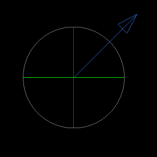
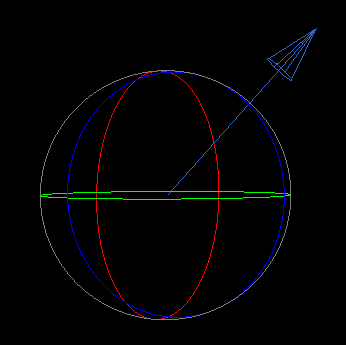
// Create a DebugLine instance with a point and a radius, and add it to the DebugDraw call
var dLine = DebugLine(Real3(0,0,0), Real3(5, 5, 0));
dLine.HeadSize = 1.0;
dLine.Color = Real4(0.2, 0.4, 0.8, 1.0);
DebugDraw.Add(dLine);

// Create a DebugSphere instance and add it to the DebugDraw call
var dSphere = DebugSphere(Real3(0,0,0), 4.0);
dSphere.Colored = true;
DebugDraw.Add(dSphere);
 The preceding code block as rendered in a 2D level
 The preceding code block as rendered in a 3D level (viewed from an angle)
DebugLine
DebugLine draws a line between two points, a start and an end. Lines can also be arrows by using the BoxHeads checkBox property, which adds a cone on the end of the line. These two points provide the minimum required settings when adding a debug line object. The DebugLine-specific member variables along with descriptions of each are listed below:
| Parameter | Description |
|---|---|
| Start | Defines the starting position of the line |
| End | Defines the end position of the line |
| Color | Defines the color of the line |
| HeadSize | Defines the size of the head at the top of the line (default shape is an arrow) |
| BoxHeads checkBox | A Boolean that when set to true changes the heads to boxes |
| DualHeads checkBox | A Boolean that when set to true places Heads on both ends of the line |
The following NadaScript shows how a debug object's member variables may be defined with properties as well as updated according to game logic:
class RotateLine : NadaComponent
{
  [Dependency] var Transform : Transform;

  [Property] var DrawLine : Boolean = false;
  [Property] var LineEnd : Real3;
  [Property] var RotDegrees : Real = 90.0;
  [Property] var LineColor : Real4 = Real4(0.2, 0.4, 0.8, 1.0);
  [Property] var LineArrowSize : Real = 1.0;

  var Angle : Real;      // The angle by which to rotate the line

  function Initialize(init : CogInitializer)
  {
    Zilch.Connect(this.Space, Events.LogicUpdate, this.OnLogicUpdate);
  }

  function OnLogicUpdate(event : UpdateEvent)
  {
    if(this.DrawLine)
    {
      // Create a DebugLine instance
      var debugLine = DebugLine(this.Owner.Transform.Translation, this.LineEnd);

      // Set debug line start to the object's translation
      debugLine.Start = this.Owner.Transform.Translation;

      // Set target angle to the desired rotation multiplied by Dt
      this.Angle += Math.ToRadians(this.RotDegrees) * event.Dt;

      // Rotate the debug line's end based on the target angle
      var endX = (this.LineEnd.X * Math.Cos(this.Angle)) - (this.LineEnd.Y * Math.Sin(this.Angle));
      var endY = (this.LineEnd.Y * Math.Cos(this.Angle)) + (this.LineEnd.X * Math.Sin(this.Angle));

      // Set the new end point
      debugLine.End = Real3(endX, endY, 0);

      // Set line color and head size
      debugLine.Color = this.LineColor;
      debugLine.HeadSize = this.LineArrowSize;

      // Add the line to the DebugDraw call
      DebugDraw.Add(debugLine);
    }
  }
}
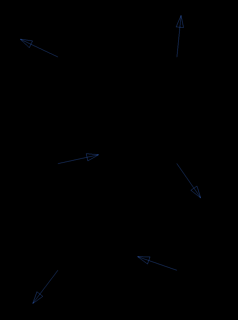
 The preceding NadaScript rendered in a 2D level
DebugTriangle
DebugTriangle draws a triangle defined by three vertices (the member variables Point0, Point1, and Point2). The DebugTriangle-specific member variables along with descriptions of each are listed below:
| Parameter | Description |
|---|---|
| {nav icon=pencil-square-o, name=Point0} | Defines the first vertex of the triangle |
| {nav icon=pencil-square-o, name=Point1} | Defines the second vertex of the triangle |
| {nav icon=pencil-square-o, name=Point2} | Defines the third vertex of the triangle |
| Color | Defines the color of the border/fill of the triangle |
The following ZIlchScript illustrates in a simple manner how consecutive triangles may be debug drawn:
class DrawTriangles: NadaComponent
{
  // The vertices for the triangle pairs
  [Property] var Vertex1: Real3;
  [Property] var Vertex2 : Real3;
  [Property] var Vertex3 : Real3;
  [Property] var Vertex4 : Real3;

  // The two colors to use for each triangle pair
  [Property] var ColorA : Real4;
  [Property] var ColorB : Real4;

  // Number of triangle pairs to draw
  [Property] var NumberOfTriangles : Real;

  function Initialize(init : CogInitializer)
  {
    Zilch.Connect(this.Space, Events.LogicUpdate, this.OnLogicUpdate);
  }

  function OnLogicUpdate(event : UpdateEvent)
  {
    // Store the x-coordinate values for each vertex
    var x1 = this.Vertex1.X;
    var x2 = this.Vertex2.X;
    var x3 = this.Vertex3.X;
    var x4 = this.Vertex4.X;

    // Get the difference between two x-coordinates that share the same y-coordinate
    var diff = this.Vertex2.X - this.Vertex1.X;
    // Loop as many times as there should be pairs of triangles
    for(var i = 0; i < this.NumberOfTriangles; ++i)
    {
      // Increase the x-coordinate by the difference
      this.Vertex1.X += diff;
      this.Vertex2.X += diff;
      this.Vertex3.X += diff;
      this.Vertex4.X += diff;

      // Create and add the first triangle
      var triA = DebugTriangle(this.Vertex1, this.Vertex2, this.Vertex4);
      triA.Color = this.ColorA;
      DebugDraw.Add(triA);

      // Create and add the second triangle
      var triB = DebugTriangle(this.Vertex2, this.Vertex3, this.Vertex4);
      triB.Color = this.ColorB;
      DebugDraw.Add(triB);
    }

    // Reset the original x-coordinate values
    this.Vertex1.X = x1;
    this.Vertex2.X = x2;
    this.Vertex3.X = x3;
    this.Vertex4.X = x4;
  }
}
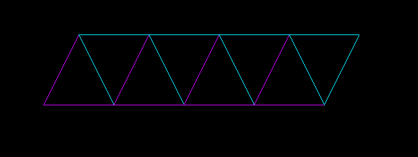
 The preceding NadaScript rendered in a 2D level